|
|
|
|
ElectricScooterParts.com Support Center
How can we help you today?
This forum is in read-only mode. Please continue to browse,
but replies are disabled for now. Why?
Freedom scooter 644 wiring diagram
Electric Scooter Parts
said
over 11 years ago
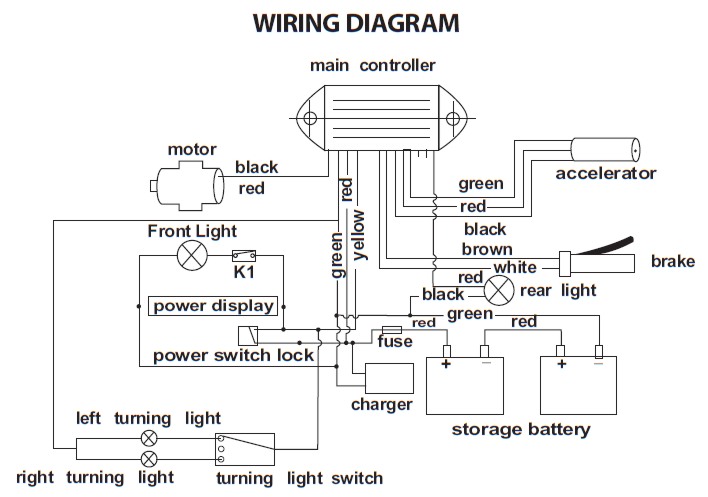
I do not have a wiring diagram specifically for the Freedom 644 electric scooter but I do have one for a Scoot-N-Go that may help.
Here is the Scoot-N-Go wiring diagram:
The throttle would be the brown and blue on mine, correct? If so, that would be connected to the motor? It sparks when I try to connect the battery.
Electric Scooter Parts
said
over 11 years ago
Most throttles have three wires which are red - black - green/blue/white. The throttle connects to the speed controller, not the motor. The speed controller is the only component that connects to the motor. It is normal for a spark to occur when connecting the battery pack to the controller.
Please let me know if you have any further questions.
Please let me know if you have any further questions.
So do I connect the battery to the motor or the controller. Like I said, all the thick wires that have only 2 wires connecting to an adapter were all disconnected, so I don't know what goes into what...
Electric Scooter Parts
said
over 11 years ago
The battery pack connects to the speed controller and not the motor. Here is a basic wiring diagram showing which parts connect to the other parts in the circuit. The battery pack usually connects to the speed controllers thick red and black wires and the motor usually connects to the speed controller thick blue and white/yellow wires (although the speed controller's thick motor wires are sometimes different colors).

Please let me know if you have any further questions.
Adam g