|
|
|
|
ElectricScooterParts.com Support Center
How can we help you today?
Terminator ES-04 Electric Scooter Wiring Schematic Help
Electric Scooter Parts
I do not have or know where to find a wiring schematic for the Terminator ES-04 electric scooter.
A new controller could be custom installed in the scooter if the battery pack, motor, key switch, and throttle wires can be determined. That would at least get the motor running. If the scooter has lights and turn signals they will be more challenging to get working than the motor. If you can live with only the motor running though then installing a new controller should not be very difficult.
You could change the type of fuse that the scooter uses by installing a different fuse holder, however I do not recommend changing the Amp rating of the fuse unless a different controller and maybe thicker gauge wires are installed. Most Terminator scooters use 20 Amp fuses.
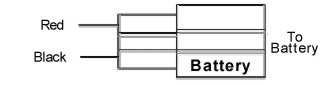
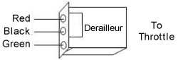
Here is an illustration of a basic electric scooter wiring diagram:

Electric Scooter Parts
It is extremely important that the battery pack's positive and negative wires are correctly wired to the controller or else the controller will be damaged, however it is not important for the motor wires to be correctly wired to the controller the first time. If the motor wires are incorrectly wired to the controller then the motor will spin in reverse and the polarity of the motor wires will need to be reversed.
The fuse should be located between the battery pack and the controller on the thick red positive wire.
Please let me know if you have any further questions.
The black and green wires are the same size as the battery cables and the yellow and red wires are about half the sizeof the battery wires are for some weird reason the black and green wires seem to be a group and the red and yellow wires have small female connectors on them.I have very limited knowledge of this kind of wiring and in this case it almost seems custom to me I will try to pull the controller off and post a pic so you can see it the blinkers and lights were cut off the front so that is a different project in it's self.There are a few of the original connectors still on the controller but that is easy enough to figure out.
The wiring harness is a mess wires all over after getting it done should I use wire mounts and electrical tape to reduce the space the harness takes up?
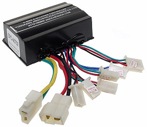
This is what my controller wires look like but not that same order.
Speed Controller SPD-24500 Installation and Wiring
Rated Voltage 24 VoltsRated For Motors Up To 500 WattsMaximum Current 30 AmpsRated For Chargers Up To 3 AmpsConversion Efficiency 95%Under Voltage Protection 31 VoltsRecommended Fuse Size 30 AmpsUnder Voltage Battery Protection: When the battery pack falls below a specific Voltage the controller turns the motor off preventing over discharging of the battery pack which extends the battery packs lifespan. (The cutoff value is approximately 31.0 Volts ± 1.0 Volts)
Motor Cut-Off During Braking: When the brakes are engaged the brake switch signals the controller to turn off the motor. *Power Connector
Red = Positive
Black = Negative
Mating Connector Item # CNX-50
Required Connection
Motor Connector
Green = Positive
Yellow = Negative
Mating Connector Item # CNX-50 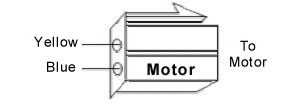
Required ConnectionThrottle Connector
Mating Connector Item # CNX-52
Required ConnectionKey Switch Connector
Mating Connector Item # CNX-51
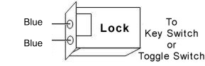
Required Connection
Battery Charger Connector
Red = Positive
Black = Negative
Mating Connector Item # CNX-51
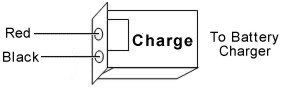
~Optional ConnectionBattery Gauge
Mating Connector Item # CNX-51
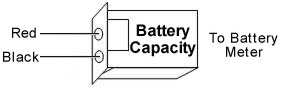
~Optional ConnectionBrake Lever Switch Connector
Mating Connector Item # CNX-51
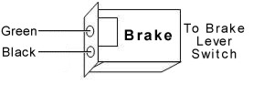
~Optional ConnectionBrake Light Connector
Mating Connector Item # CNX-51
~Optional Connection*The power connector should be the last connection made.
*Fuse or circuit breaker protection is required between speed controller and battery pack.
~Optional Connections do not need to be hooked up for the speed controller to operate.
Only my blue wire is green,still the same dilemma as before no power when key is turned on fuse is good but I still have no idea why it wont work maybe I need to start over again and see if I am making all the connections in the right order.
Electric Scooter Parts
this is my controller I know it's kinda hard to see but the product type is there.I really hope to figure out how to wire this right its a 2 plug 4 wire controller so that should narrow it down some.Not sure how well you can see it but the Black & Green wires are the thickest wires on there.
Electric Scooter Parts
If you can not get the old controller to operate then you may want to consider installing a new controller. That way you can know that the controller is good and will have wiring directions that indicate how to wire it into the scooter. Please let me know if you have any questions.
Well the diagram that I found shows the green and red wires go to the battery but that really doesn't seem right going to try it out and see if it works and if that is the case then the black would be the positive of the motor.I wish the previous owner would not have cut all the connectors off of the scooters wiring harness but I will make do with what I have on hand.Really hoping to have it up and going by tuesday need a way around for my b-day.
Does this wiring sound like it would be right to you I have written out many different ways to wire it but this seems the most logical to me,tell me what you think.
2 medium wires:
controller Red = Motor +
controller yellow = to harness orange to + on/off switch from fuse + connects to battery +
2 Large wires:
controller Green = Battery -
controller Black = Motor -
2 medium wires:
controller Red = Motor +
controller yellow = to harness orange to + on/off switch from fuse + connects to battery +
2 Large wires:
controller Green = Battery -
controller Black = Motor -
Not sure about this setup either but I at least wanted to get your thoughts on it.
Hideki_Shino
I recently obtained this model of scooter and discovered that it has fried wiring in a number of places so I am wondering if I can just rewire everything with new controller and other needed parts but I do not have the owner's manual for my scooter and obtaining one that is complete seems to be more of a challenge than one would expect,my question is can I change what fuse type this scooter takes and if so then what wiring guide will be most helpful in the total rewiring of my scooter?