|
|
|
|
ElectricScooterParts.com Support Center
How can we help you today?
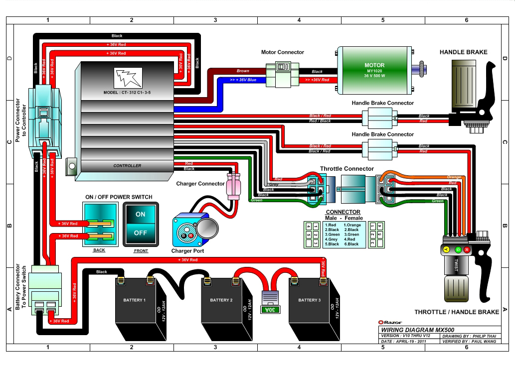
Power Switch Circuit for Thumb Throttle on 36V Controller
Wow, Bing Images came through in the end. It took me right back here to a schematic that cleared it up. I thought that the on/off switch was to kill the motor controller somehow. It appears at best to be an auxillary power switch for things like lights perhaps. I can make use of it with the Arduino microcontroller circuit I'm adding in to relay in the power and provide safety interlocks.
http://www.electricscooterparts.com/wiringdiagrams/razor-mx500-wiring-diagram-v10-12.jpg
Electric Scooter Parts
On the SPD-CT312C1 controller's power connector, the thin red wire goes to the charger port's thin red wire and allows the battery pack to be recharged when the power switch is off. The thick red wire is the main power input wire for the controller. When the thick red wire is in an open circuit with the battery pack the controller is off, and when it is in a closed circuit the controller is on.
Sean Miller
I just purchased a 36V 650W controller and a thumb throttle with a battery indicator circuit and power switch:
https://electricscooterparts.com/hookup/SPD-CT312C1.htm
https://electricscooterparts.com/manuals/THR-138.html
I'm not understanding the power switch circuit. On the controller side, there is a small red wire that has no voltage when the large red and black wires that it shares a connector with are hooked to the battery.
On the throttle side, it appears the two power switch wires also have no voltage when unconnected. The power switch simply allows current to flow from one wire to the other.
How do I hook up the power switch circuit?
Thanks,
Sean